Connectors and Signal Integrity
Definition
A connector determines what kind of signal a cable carries and how well that signal is protected over distance. Most professional audio lines are balanced. A balanced line uses two signal conductors and a shield: on an XLR connector, pin 1 is the shield or ground, pin 2 is hot (positive) and pin 3 is cold, the convention set by AES14 and by IEC 60268-12. Interference induced along the cable appears almost equally on both conductors, and the differential input of the receiver subtracts one conductor from the other, which cancels this common-mode noise. The rejection depends on the two conductors having equal impedances to ground. Many outputs also send the signal in opposite polarity on the two conductors, although Bill Whitlock (Jensen Transformers) has shown that this signal symmetry plays no part in the rejection.

The guide
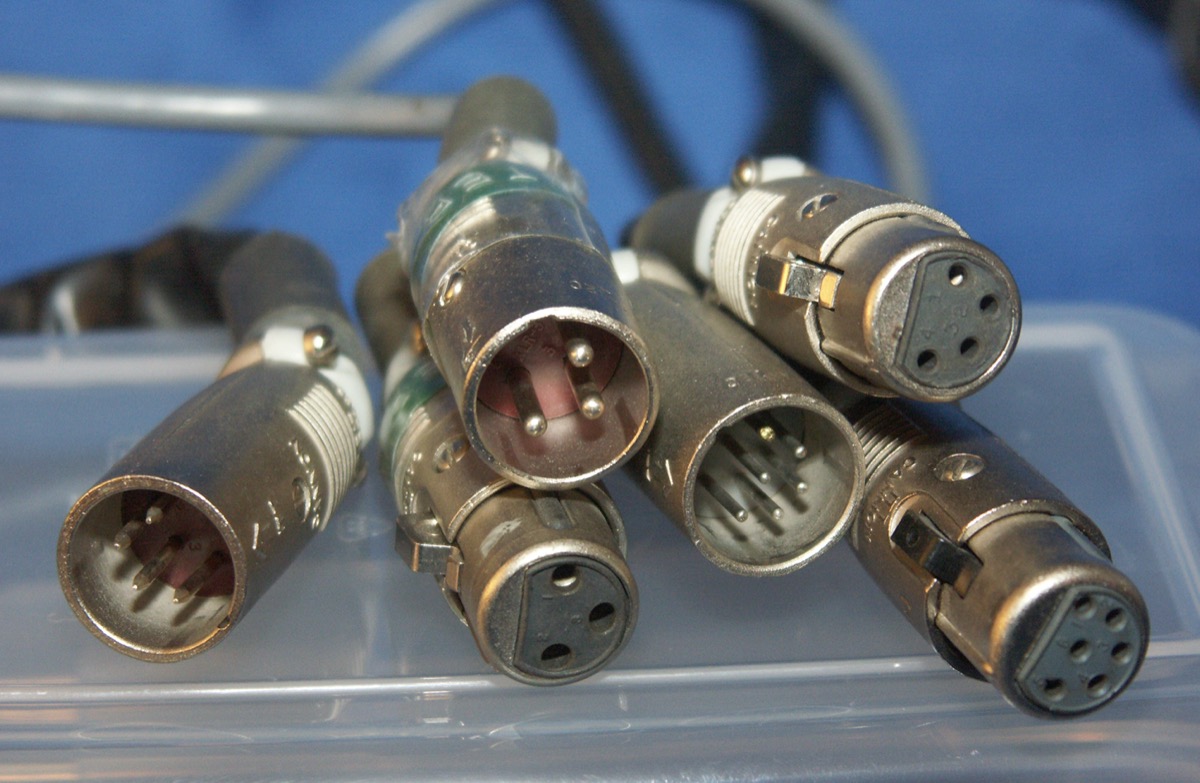
Common-mode rejection lets a balanced line run tens of metres near dimmers and motors without audible hum. XLR is the standard connector for balanced microphone and line signals. A TRS jack carries either a balanced mono signal or an unbalanced stereo signal depending on its wiring, and a TS jack is always unbalanced, so TS cables are kept short.
Condenser microphones need power, which travels over the same balanced cable as phantom power. IEC 61938 defines 48 V phantom power (P48) along with 12 V and 24 V variants. A correctly wired balanced dynamic microphone is unaffected, because the same voltage is present on pins 2 and 3. Ribbon microphones are at risk when a cable is miswired or a line is patched while live: Royer Labs reports that the voltage can then reach the ribbon and stretch it, and some vintage ribbons can be damaged by phantom power itself.
Loudspeaker connections carry currents of several amperes instead of the millivolts of a microphone signal. They use locking Speakon connectors, which Neutrik designs for high-current loudspeaker loads and not for microphone or line signals. Speaker-level and line-level connections are never interchangeable, and connecting an amplifier output to a line input can destroy that input. Shielding keeps electromagnetic interference out of the signal, and noise added by a poorly shielded cable cannot be removed later by the console.
The rule
The connector is chosen according to the type and level of the signal it carries.
Glossary terms
Sources
- AES14-1992 (r2004), XLR-type polarity and gender : broche 1 masse, broche 2 positive, broche 3 négative ; document fondé sur l'IEC 268-12 · op316.com
- IEC 61938:2018 : alimentation fantôme P12, P24 et P48 (48 V via 2 × 6,8 kΩ) · cdn.standards.iteh.ai
- R. Elliott, Phantom Power (ESP) : valeurs P48 de l'IEC 61938, résistances appairées de 6,81 kΩ · sound-au.com
- B. Whitlock, Balanced Lines in Audio Systems: Fact, Fiction, and Transformers, JAES vol. 43, 1995 : interfaces symétriques et transformateurs · academia.edu
- B. Whitlock, Design of High-Performance Balanced Audio Interfaces (Jensen) : la symétrie du signal ne joue aucun rôle dans la réjection ; les impédances des deux conducteurs par rapport à la masse doivent être égales · sound-au.com
- Royer Labs, Ribbon Mics and Phantom Power, fantôme sans danger en conditions normales ; risques : câbles mal câblés, patch sous tension, certains rubans anciens · royerlabs.com
- Shure, Top 8 Microphone Myths Exposed : un dynamique symétrique correctement câblé n'est pas affecté par l'alimentation fantôme · shure.com
- Neutrik, speakON cable connectors : connecteurs verrouillables pour liaisons amplificateur/enceinte à fort courant · neutrik.com